
![]() Released MAC version of CompTIA® A+™ 220–1001 certification exan. CompTIA A+ core1 (220–1001) practice tests for Mac offered by SimulationExams.com conform to the latest exam objectives.
Released MAC version of CompTIA® A+™ 220–1001 certification exan. CompTIA A+ core1 (220–1001) practice tests for Mac offered by SimulationExams.com conform to the latest exam objectives.
The exam topics covered in the practice tests are Mobile Devices, Networking, Hardware, Virtualization, and Cloud Computing and Hardware and Network Troubleshooting. The practice test is prepared by CompTIA certified experts in the field and it may help in boosting the score. The exam simulator is prepared with different types of questions that you may encounter in actual exam, including:
- Multiple Choice Single Answer (MCSA)
- Multiple Choices Multiple Answers (MCMA)
- Exhibit type
The A+ core1 practice tests contain 300+ highly relevant questions with flashcards. The practice tests provides a timed test environment and each question is categorized that helps you to prepare for the actual exam by assessing areas that needs improvement. Customization of exam configuration such as time, score, pass percentage is possible. A detailed scorecard is generated after submitting the exam, and the review feature allows to cross-check the incorrect answers.
You may also be interested in Android and iOS versions for mobile devices. One can download the apps by clicking the below links
The Windows version of the software is available here:
Disclaimer: Simulationexams.com is neither associated nor affiliated with CompTIA® or any other company. A+™, Network+™, Security+™, Server+™ are trademarks of CompTIA® and duly acknowledged.
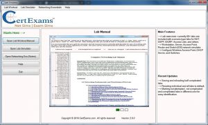 The lab sim contains several labs for hands on practice ensuring thorough preparation before appearing for the Network+ exam. Several labs on networking fundamentals, DNS, DHCP, and network troubleshooting have been provided. Other practice tests available from Comptia stream are A+ Core 1, A+ Core 2, Security+ and Server+.
 Simulationexams.com, leading provider of practice exams and network simulators, recently released practice tests for Comptia®. A+ Core1®. and Comptia A+ Core2®. exams. Currently, the practice tests are available for mobile devices including Android phones and Apple iOS phones. As you all might be aware, the existing exams, 220-901 and 220-902 are going to be retired by 31st July 2019 (English language version). The same are going to be replaced by 220-1001 (A+ Core 1) and 220-1002 (A+ Core 2) respectively. A few significant inclusions are Windows 10 operating system, and enhancement in virtual services such as Cloud services. Mobile devices and security have also been given more importance in recent revision. Over all, 85% of the syllabus remains to be same as that of older one.
 Simulationexams.com, leading practice tests provider, released