What is Spanning Tree Protocol: In computer networking, data packets are forwarded from one network node to another as the packet travels from source to destination. However, in Ethernet networks, it is quite possible that these packets (in strict sense, these are called frames as they traverse at layer-2 of the OSI layer format within LAN) have multiple paths to the next hop address. Consider the simple figure given below:
 Assume that Frame 1 originating at SwitchA needs to reach destination SwitchD. As may be seen in the adjacent figure, Frame 1 originating a SwitchA has multiple paths to reach SwitchC. If the redundant path is not blocked, it may result in a loop. i.e. the same frame Frame 1 may be broadcast at SwitchC and again come back via SwitchB. Remember that bridges and layer-2 switches natively send frames to all ports other than the port on which the frame is received.
Note: STP allows redundancy in Layer-2 networks. For example, in the above network, if the link from SwitchA to SwithcC fails, then the frames are transmitted via SwitchB.
The exact path that a frame takes when traversing from one node to another within a LAN depends on the STP configuration, and we discuss this later.
In summary, Spanning Tree Protocol (STP) is a network protocol designed to prevent layer 2 loops and it’s standardized as IEEE 802.D protocol.
Fundamentals of simple STP: STP runs within LANs, ie. on Layer-2 devices such as simple switches and bridges. If you are sitting in a office environment, it is very likely that you are connected to your office LAN consisting of switches and bridges. As mentioned earlier, the single most important feature of STP is to prevent loops within a network, and at the same time offering network redundancy. We discuss the mechanisms that are followed to achieve this objective.
STP uses what is known as BPDU (Bridge Protocol Data Unit), a multicast frame, to share information about switch and its interface connections. Switches within LAN use BPDUs to learn the LAN topology. BPDU frames are sent out as multicast in every two seconds. The LAN requires a reference node that controls all operations, and that node is Root Bridge.
Root Bridge is selected using the following criteria in STP:
- The switch with the lowest Bridge Priority field becomes the Root Bridge.
- If there is a tie between switches having the same priority value, then the switch with the lowest MAC address becomes the Root Bridge.
Default priority value is 32768. If you want one switch to be Root Bridge, change its priority value to less than 32768. Selection process of Root Bridge runs each time when you add or remove a switch or a bridge in the LAN topology (note that switch and bridge are used interchangeably here for understanding). If other switches in network do not receive BPDUs from Root Bridge within a specified time (usually 20 seconds), they assume that Root Bridge had failed and an election process to choose a new Root Bridge will occur.
Note: There are different flavors of STP, simplest being CSTP (Common STP) that will have only one LAN. In the entire article, we are assuming that VLANs are not used within the LAN network. When using VLANs, multiple instances of STP are present. These are defined by Multiple Spanning Tree (MST), Per-VLAN Spanning Tree (PVST) and Per-VLAN Spanning Tree Plus (PVST+). Once the concept is clear, it can be extended easily to networks with VLANs.
Root Bridge Election Process: Each BPDU consists of the following:
- Root Bridge ID or Root BID – BID of the switch that the sender of this BPDU believes to be the root switch
- Sender’s Bridge ID – BID of the switch sending this Hello BPDU
- Cost to the Root Bridge – The STP cost between this switch and the current root
- Timer values on Root Bridge – Hello Timer, Max Age Timer, Forward Delay Timer
Example:
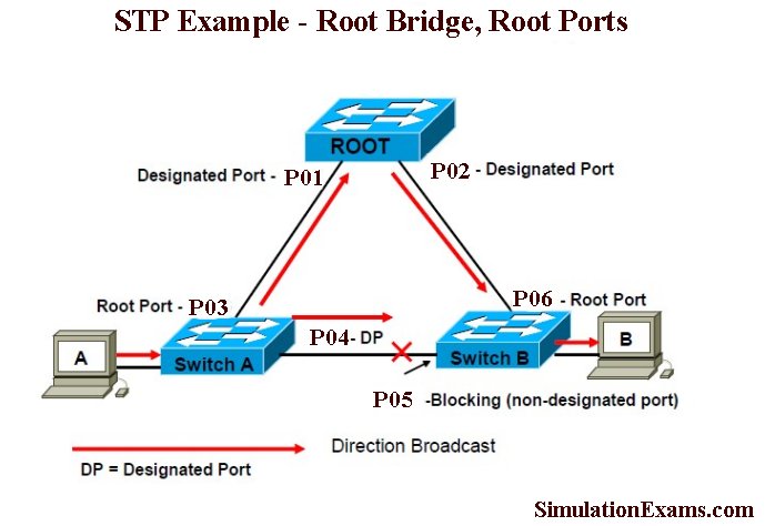
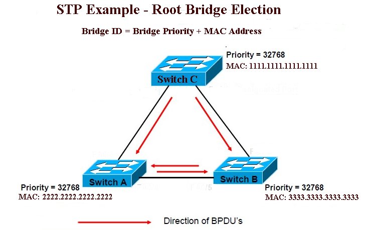 In the figure above, all the three switches (Switch A, Switch B, and Switch C) are propagating BPDUs as shown. The Root Bridge is not yet elected. Switch C has the lowest MAC address and hence elected as the Root Bridge (Bridge priorities are same for all three switches here, otherwise, Switch with higher priority value would have been elected as Root irrespective of the MAC addresses). The figure below shows the final network topology after STP convergence. Note that P05 port is blocked with the assumption that all links have same bandwidth.
To recapitulate, initially each switch within the LAN assumes itself as the root bridge and sends out BPDUs. However, when a BPDU with better Bridge ID (BID) is received, it replaces Root Bridge ID in it’s own BPDU with that of the superior BID. This process continues till every switch with in LAN agrees on which switch has the lower BID, and hence deserves to be the Root Bridge.
Non-Root Bridge: All other switches in LAN except Root Bridge are known as non-Root Bridges. Non-Root Bridge receives updates from Root Bridge and update its STP database.
Port Costs: STP assigns each port within LAN a cost, called port cost. Port cost is used to choose the best path when multiple paths are available between two switches. Port cost is determined by the bandwidth of connected media link. Switch always use the lowest port cost to forward the frames. As may be seen from the table below, higher the bandwidth.. lower the port cost.
Two set of port costs exist.
Bandwidth Old Cost Value New Cost Value
10 Gbps 1 2
1 Gbps 1 4
100 Mbps 10 19
10 Mbps 100 100
Note: In STP, lower number reflects better ranking.
Root Port: Spanning Tree Root Port selection process in a Non-Root Switch is done using steps below:
- Select the port with the lowest Path Cost to the Root Bridge as the Root Port, (applicable only if a Non-Root Switch has two or more paths to reach the Root Bridge).
- If there is tie, Non-Root Switch will select the local port which is receiving lowest Bridge ID from neighbor Switch (Advertiser) as the Root Port.
- If there is a tie, it will select one with lowest received port-priority
- If there is a tie, Non-Root Switch will select the port which receives the lowest physical port number from neighbor Switch as the Root Port. This is the last tie breaker
Just remember the following:
Lowest Root Path Cost (tie) -> Port Receiving the Lowest Bridge id (tie)-> Lowest Received Port-Priority (tie) -> Lowest Advertised Port Identifier
Other related terms:
Designated Port: Designated port is the port that is selected as having the lowest port cost. Designated port would be marked as forwarding port.
Non-Designated Port: Non-designated port is the port that is selected as having the higher port cost than the designated port. Non-designated port would be marked as blocking port and will not forward any frames. Of course, if there is any change in topology of the network, the same port may become a designated port.
Forwarding Port: Forwarding port is used to forward the frames with in the network.
Blocking Port: Blocking port remains disabled to remove loops. in the network.
Summary of Selection of Root Bridge, Root Port, and Designated Ports:
1. Lowest bridge ID (Priority+MAC Address) switch becomes the Root-Bridge
2. Each non-root bridge should have ONE root port (RP) which is the port having lowest path-cost to Root Bridge.
3. All ports in Root Bridge become Designated Ports (DP)
4. Each segment should have one Designated Port (DP)
5. All RP/DPs will be in FORWARDING state & all other ports will be in BLOCKING state.
References:
- https://www.tutorialsweb.com/networking/tcp-ip/index.htm
 Tutorialsweb.com, a leading professional skills development site, recently released an