Now a days, almost every organizational network uses VLANs, and it’s un-imaginable to have a LAN without a VLAN.
Traditionally, a Local Area Network (LAN) is a network of computers located within the same geographical area. Today, Local Area Networks are defined as a single broadcast domain. This means that if a host broadcasts information on LAN, the broadcast will be received by every other host on the same LAN. Broadcasts are prevented from leaving a LAN by using Layer-3 addressing, provided by a router or a layer-3 switch. The disadvantage of using routers (in comparison with L3 switch) is that they normally take more time to process incoming packets. Given below are some of the advantages of VLANs:
- VLANs enable logical grouping of end-stations that are physically dispersed on a network: When users on a VLAN move to a new physical location but continue to perform the same job function, the end-stations of those users do not need to be reconfigured. Similarly, if users change their job functions, they need not physically move: changing the VLAN membership of the end-stations to that of the new team makes the users’ end-stations local to the resources of the new team.
- VLANs reduce the need to have routers deployed on a network to contain broadcast traffic. Flooding of a packet is limited to the switch ports that belong to a VLAN.
- Confinement of broadcast domains on a network significantly reduces traffic. By confining the broadcast domains, end-stations on a VLAN are prevented from listening to or receiving broadcasts not intended for them. Moreover, if a router or a layer-3 switch is not connected between the VLANs, the end-stations of a VLAN cannot communicate with the end-stations of the other VLANs.

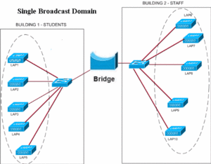
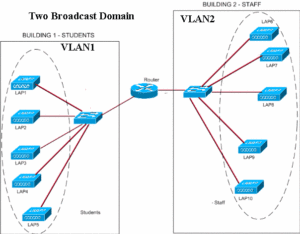
The figure shows a LAN network using single broadcast domain. As a result, both the groups (staff and students) will be on the same LAN. A bridge works at layer-2 of OSI layer and simply forward traffice from either end. Both Students and Staff networks form a single LAN. The next figure shows how a VLAN makes difference to the broadcast domain. In this figure, the two LANs have been segregated using a router.
 A router doesn’t forward broadcast traffic and therefore, users in VLAN1 will not be able to communicate with users in VLAN2, unless the router is configured to forward traffic from VLAN1 to VLAN2 and vice versa. As we can understand from the explanation above, configuring VLANs requires a layer-3 address mapping. Each VLAN in a VLAN network will have a unique IP address which would be used to identify the VLAN, and forward traffic from one VLAN to another VLAN. We can also use a Layer-3 Switch instead of a router for this purpose. The benefit of using Layer-3 switch is shorter response times.
Static and Dynamic VLANs: VLANs may broadly be categorized in to Static and Dynamic VLANs.
Static VLANs: In a static VLAN, the network administrator creates a VLAN and then assigns switch ports to the VLAN. Static VLANs are also called port-based VLANs. The association with the VLAN does not change until the administrator changes the port assignment. End-user devices become the members of VLAN based on the physical switch port to which they are connected.
The ports on a single switch can be assigned to multiple VLANs. Even though workstations are connected to different ports on a same switch, traffic will not pass between them if the connected ports are on different VLANs. We need a layer 3 device (typically a Router) to enable communication between two VLANs.
Dynamic VLANs: In a dynamic VLAN, the switch automatically assigns the port to a VLAN using information from the user device like MAC address, IP address etc. When a device is connected to a switch port the switch queries a database to establish VLAN membership. A network administrator must configure VLAN database of a VLAN Membership Policy Server (VMPS).
Dynamic VLANs support instant movability of end devices. When we move a device from a port on one switch to a port on another switch, the dynamic VLANs will automatically configure the membership of the VLAN.
So, how VLANs are identified by a switch or router? How they are different from a packet that doesn’t use VLAN? VLANs are identified in a network by what is called as a “tag”. Frame tagging is used to identify the VLAN that the frame belongs to in a network with multiple VLANs. The VLAN id is placed on the frame when it reaches a switch from an access port, which is a member of a VLAN. That frame is then forwarded out the trunk link port or other ports with same VLAN id. Each switch in network can see VLAN id and accepts the frame if it has any ports that are members of the same VLAN. If it doesn’t have any port with matching VLAN id, it simply ignores the frame. One more thing could happen. If the switch has a “trunk” link, the frame is forwarded across the “trunk port” to another switch.
A trunk port is a port that is assigned to carry traffic for all the VLANs, a process known as trunking. Trunk ports mark frames with unique identifying tags – either 802.1Q tags or Inter-Switch Link (ISL) tags (not both at the same time, network admin chooses the tag type at the time of configuring the network)– as they move between switches. Therefore, every single frame can be directed to its designated VLAN.
An Ethernet interface can either function as a trunk port or as an access port, but not both at the same time. A trunk port is capable of having more than one VLAN set up on the interface. As a result, it is able to carry traffic for several VLANs at the same time.
If a switch receives untagged Ethernet frames on its Trunk port, they are forwarded to the VLAN that is configured on the Switch as native VLAN. Both sides of the trunk link must be configured to be in same native VLAN. It is not usual for a Switch port configured as a trunk port to receive untagged Ethernet frames. But it will happen if you are using Cisco VOIP phones in your network.
Note: The IEEE committee that defined 802.1Q decided that for backward compatibility it was desirable to support native VLAN, a VLAN that is not associated explicitly to any tag on an 802.1Q link. This VLAN is implicitly used for all the untagged traffic received on an 802.1Q capable port (Trunk port).
Frames from all VLANs are carried across the trunk link containing the 802.1Q or ISL tag, except for frames belonging to VLAN 1. By default, frames from VLAN 1 belong to native VLAN, and are carried across the trunk untagged. Frames from the native VLAN, VLAN 1, are carried across this trunk link untagged.
Now, we have several VLANs and routers or layer-3 switches have been setup to communicate between VLANs. However, it becomes very difficult to add VLANs, or modify VLANs on several switches. VTP, short for VLAN Trunking Protocol (a Cisco proprietary protocol) makes that task less cumbersome by communicating the changes to VLANs.
VTP is a Layer 2 messaging protocol that maintains VLAN configuration consistency by propagating the addition, deletion, and renaming of VLANs within a VTP domain. A VTP domain (also called a VLAN management domain) is made up of one or more network devices that share the same VTP domain name and that are interconnected with trunks. VTP minimizes misconfigurations and configuration inconsistencies that can result in a number of problems, such as duplicate VLAN names, incorrect VLAN-type specifications, and security violations. With VTP, you can make configuration changes centrally on a single network device and have those changes automatically communicated to all the other network devices in the network.
VLAN Trunk Protocol (VTP) reduces network administration in a switched network by auto propagating the latest VLAN information. When you configure a new VLAN on one VTP server, the VLAN is distributed through all switches in the domain. This reduces the need to configure the same VLAN everywhere.
Configuring VLANs:
VLANs provide logical segmentation of networks by creating separate broadcast domains. A VLAN can span multiple physical network segments. The end-stations belonging to a VLAN are related by function or application.
For example, end-stations in a VLAN might be grouped by departments, such as engineering and accounting, or by projects, such as release1 and release2. Because physical proximity of the end-stations is not essential in a VLAN, you can disperse the end-stations geographically and still contain the broadcast domain in a switched network.
You can manage VLANs by creating, deleting, or displaying information about them.
Note: VTP is a Cisco-proprietary protocol that is available on most of the Cisco Catalyst series products. Similar protocol is available with all other make switches, such as Juniper switches.

