1.0 Personal Computer Components
1.1 Identify the fundamental principles of using personal computers
Form Factor (e.g. ATX , micro ATX)
ATX (Advanced Technology Extended) is a full size board measuring 12" wide by 9.6" deep. ATX has 6-pin mini keyboard connector. Also, it has double row single power supply connector providing +/-5V, +/-12V, and +3.3V.
MicroATX is a small motherboard size of 9.6" x 9.6". Compared to full size ATX, microATX have smaller number of I/O slots. For example, full ATX can have 5 PCI slots, whereas MicroATX can have up to 3/4 PCI stots only. The chief advantages over ATX is reduced size, and power requirements.
Components
A typical ATX PC motherboard with constituent components is given below:
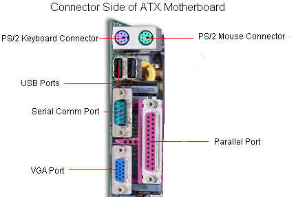
The important constituent components of an ATX Motherboard are given below:
1. Mouse & keyboard: Keyboard Connectors are two types basically. All PCs have a Key board port connected directly to the motherboard. The oldest, but still quite common type, is a special DIN, and most PCs until recently retained this style connector. The AT-style keyboard connector is quickly disappearing, being replaced by the smaller mini DIN PS/2-style keyboard connector.
You can use an AT-style keyboard with a PS/2-style socket (or the other way around) by using a converter. Although the AT connector is unique in PCs, the PS/2-style mini-DIN is also used in more modern PCs for the mouse. Fortunately , most PCs that use the mini-DIN for both the keyboard and mouse clearly mark each mini-DIN socket as to its correct use. Some keyboards have a USB connection, but these are fairly rare compared to the PS/2 connection keyboards.
2. USB (Universal serial bus): USB is the General-purpose connection for PC. You can find USB versions of many different devices, such as mice, keyboards, scanners, cameras, and even printers. a USB connector's distinctive rectangular shape makes it easily recognizable.
USB has a number of features that makes it particularly popular on PCs. First, USB devices are hot swappable. You can insert or remove them without restarting your system.
3. Parallel port: Most printers use a special connector called a parallel port. Parallel port carry data on more than one wire, as opposed to the serial port, which uses only one wire. Parallel ports use a 25-pin female DB connector. Parallel ports are directly supported by the motherboard through a direct connection or through a dangle.
4. CPU Chip : The central processing unit, also called the microprocessor performs all the calculations that take place inside a pc. CPUs come in Variety of shapes and sizes.
Modern CPUs generate a lot of heat and thus require a cooling fan or heat sink. The cooling device (such as a cooling fan) is removable, although some CPU manufactures sell the CPU with a fan permanently attached.
5. RAM slots: Random-Access Memory (RAM) stores programs and data currently being used by the CPU. RAM is measured in units called bytes. RAM has been packaged in many different ways. The most current package is called a 168-pin DIMM (Dual Inline Memory module).
6. Floppy controller: The floppy drive connects to the computer via a 34-pin ribbon cable, which in turn connects to the motherboard. A floppy controller is one that is used to control the floppy drive.
7. IDE controller: Industry standards define two common types of hard drives: EIDE and SCSI. Majority of the PCs use EIDE drives. SCSI drives show up in high end PCs such as network servers or graphical workstations. The EIDE drive connects to the hard drive via a 2-inch-wide, 40-pin ribbon cable, which in turn connects to the motherboard. IDE controller is responsible for controlling the hard drive.
8. PCI slot: Intel introduced the Peripheral component interconnect bus protocol. The PCI bus is used to connect I/O devices (such as NIC or RAID controllers) to the main logic of the computer. PCI bus has replaced the ISA bus.
9. ISA slot: (Industry Standard Architecture) It is the standard architecture of the Expansion bus. Motherboard may contain some slots to connect ISA compatible cards.
10. CMOS Battery: To provide CMOS with the power when the computer is turned off all motherboards comes with a battery. These batteries mount on the motherboard in one of three ways: the obsolete external battery, the most common onboard battery, and built-in battery.
11. AGP slot: If you have a modern motherboard, you will almost certainly notice a single connector that looks like a PCI slot, but is slightly shorter and usually brown. You also probably have a video card inserted into this slot. This is an Advanced Graphics Port (AGP) slot
12. CPU slot: To install the CPU, just slide it straight down into the slot. Special notches in the slot make it impossible to install them incorrectly. So remember if it does not go easily, it is probably not correct. Be sure to plug in the CPU fan's power.
13. Power supply plug in: The Power supply, as its name implies, provides the necessary electrical power to make the pc operate. the power supply takes standard 110-V AC power and converts into +/-12-Volt, +/-5-Volt, and 3.3-Volt DC power.
The power supply connector has 20-pins, and the connector can go in only one direction.
IDE (Integrated Drive Electronics), also known as ATA or PATA (renamed Parallel ATA, to differentiate from Serial ATA or SATA) is used with IBM compatible hard drives. IDE and its successor, Enhanced IDE (EIDE), are the commonly used with most Pentium computers..
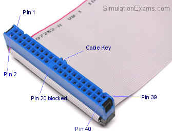
Figure: A 40-pin IDE cable connector
Enhanced IDE (EIDE) is the enhanced version of IDE technology, and supports faster access to the hard disks.
Small Computer Systems Interface (SCSI): SCSI is commonly used with server grade machines. IDE supports only two drives (one master drive and one slave drive) per channel, whereas SCSI can support 8 or more hard drives. There are different versions of SCSI available today. Different versions of SCSI include the following:
The various SCSI bus standards primarily differ in the following:
For example, SCSI-I has a throughput of 5MB/sec, where as SCSI-3 can go up to 40MB/sec.
Serial ATA (SATA): Serial ATA (SATA) is a next generation technology based on ATA, and for transfer of data to and from a hard disk. Earlier, ATA was used to mean parallel transfer of bits between the motherboard and the hard drive. However, with the advent of SATA, traditional ATA was named as PATA (Parallel ATA). IDE/EIDE is usually associated with PATA.
Memory Slots/Modules: Memory modules are printed circuit cards made up of memory chips, and a few other passive components. Normally, memory modules are the those that get installed on the motherboard's memory slots, and you don't handle individual memory chips. The following are the prominently used memory modules (also called memory cards):
Dual In-Line Memory Modules (DIMM):
DIMMs are very similar to SIMMs. The major difference is that a DIMM has two different signal pins on each side of the module as shown in the figure. One big advantage of DIMM is that only one module can be inserted into the motherboard, whereas you need two SIMMs (paired) when working with 64-bit microprocessors like Pentium II and above. Since SIMM provides only 32-bit bus, you need to use 2-SIMMs paired together with any modern 64-bit processor.
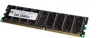
Typical DIMM package (using DDRAM):
Memory size: 256MB
Pins:168 pin
Rambus In-Line Memory Module (RIMM):
Rambus inline memory modules (RIMMs) use Rambus Dyamic RAM (RDRAM) chips.
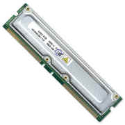
A RIMM package using RDRAM
Double Data Rate:
DDR modules are also called DIMMs (Dual-In-Line-Memory Module). A typical DDR module (DIMM) is shown above. The DIMM package using DDR is twice as fast as the one using SDRAM.
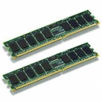
Memory Size: 2X512MB
Memory Speed: 400MHzPC3200
Memory Type: Dual Channel DDR
Pins: 184
Micro Processors, and Socket Types:
Micro processor, also called CPU (Central Processing Unit), is a major component of a micro computer. We discuss various CPUs starting from Pentium IV, and onwards.
Socket 478:
Socket 478 is a PGA socket used by Intel Pentium 4 microprocessor family (not all P IV family processors support Socket 478)..
Socket type: Socket 478 (mPGA478B)
Front Bus Frequencies: 400 MHz - 800 MHz (100 MHz - 200 MHz QDR)
Socket size: 1.38" x 1.38" (3.5 x 3.5 cm)
Number of contacts: 478
Compatible package types:
478-pin micro FC-PGA
478-pin micro FC-PGA2
Compatible processors:
Processors Intel Pentium 4 (1.4 - 3.4 GHz)
Intel Celeron (1.7 - 3.2 GHz)
Celeron D (to 3.2 GHz)
Intel Pentium 4 Extreme Edition (3.2, 3.4 GHz)
This socket has currently been replaced with socket 775.
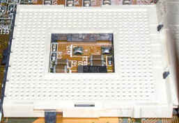
Socket A (Socket 462): Socket A (also called Socket 462) is a PGA socket compatible with AMD K7 family of processors.
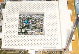
Socket A
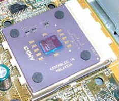
Processor for Socket A
Bus Frequencies: 100 MHz, 133 MHz, 166 MHz and 200 MHz
Number of contact pins: 462 pin holes
Compatible Processors include the following:
AMD Athlon (650 MHz - 1400 MHz)
AMD Athlon XP (1500+ - 3300+)
AMD Duron (600 MHz - 1800 MHz)
AMD Sempron (2000+ - 3300+)
AMD Athlon MP (1000 MHz - 3000+)
Compatible package types:
462-pin ceramic Pin Grid Array (PGA) package, 462-pin organic PGA
Slot A: Slot A is used by AMD's Athlon family of processors. It has 242 contacts, physically similar to that of Intel's Slot 1. But Slot A is electrically different from that of Slot 1.
Slot 2: Slot 2 is a 330 contact version of Slot 1. Intel's Xeon processor uses Slot 2. The Slot 2 cartridge may house as many as four processors and an L2 cache.
Slot 1: Slot 1 is a Slot-type connector. This connector is compatible with Pentium II family of processors, and some of low-end Celeron processors. Pentium III was the last microprocessor family that used the Slot 1.
BIOS / CMOS / Firmware
BIOS stands for Basic Input/Output System. It contains basic instructions to interact with various hardware modules such as Motherboard controllers or that of interface cards. BIOS is the software that is run by a computer when first powered on.
A computer motherboard inevitably contains a BIOS chip in the form of an onboard PROM, EPROM or flash memory. When the computer is powered on, it performs diagnostic tests on the computer hardware devices such as hard drive, FDD, and memory. It searches for other BIOS's on the plug-in boards, and takes care of them. It then loads the operating system and passes control to OS. The BIOS accepts requests from the drivers as well as the applications as shown in the figure below.
BIOS is also known as PC firmware because it is an integral part of the motherboard.
Firmware on adapter cards: A computer can contain several BIOS firmware chips. The motherboard BIOS is normally used to access basic hardware components such as the keyboard, floppy drives, and hard disk controllers. Adapter cards such as SCSI, RAID, and video boards may include their own BIOS software.
Firmware generally available in different forms:
1. EPROM (Erasable Programmable ROM), for updating a BIOS firm using EPROM, you may need to get a new chip from the manufacturer.
2. EEPROM (Electrically Erasable Programmable ROM), you can update a BIOS firmware using EEPROM using "boot to floppy", and running the Firmware update program.
3. Flash ROM - faster at rewriting the chip
A typical BIOS chip used on motherboards is shown in the figure below. Though it is a square-type PLCC package, BIOS chips come in different forms. Figure 2 shows the BIOS after insertion into the socket.:
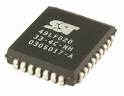
BIOS chip
BIOS chip after insertion into a socket.
Chipsets
A chipset forms an integral part of any Computer motherboard. Chipsets provide the interfaces between all of the PC's subsystems. PC chipsets, usually mean anywhere between one to four chips that include built-in controllers for almost all common peripherals. The Northbridge/Southbridge chipset architecture has been widely used in personal PCs. The Northbridge part handles high-speed channels like memory access, while Southbridge manages lower-speed devices such as IO cards, mouse, keyboard, etc.
Riser card
A Riser card connects directly into the computer motherboard and provides the ability for additional expansion cards to be added to the computer.
Daughter board
A daughter board connects to the Motherboard directly, and provides additional functionality. Hence the name daughter board. The added functionality may be something like networking, modem, etc.
Disclaimer: Simulationexams.com is not affiliated with any certification vendor, and Sim-Ex™ Practice Exams are written independently by SimulationExams.com and not affiliated or authorized by respective certification providers. Sim-Ex™ is a trade mark of SimulationExams.com or entity representing Simulationexams.com.A+™ is a trademark of CompTIA® organization.