Serial Ports:
The serial port is an Asynchronous port which transmits data one bit of data at a time. Serial port hardware usually consists of a UART (Universal Asynchronous Receiver/Transmitter).
Most commonly used serial ports are given below:
1. DB9:
DB9 adheres to the RS-232c interface standard. It has 9 pins as shown in the figure. The connector is "D" shaped, and easy to recognize. The function of each pin is described below.
Outline Diagram of DB-9
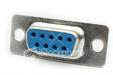
DB-9 Female Connector
Pin Description:
| Pin # | Pin Description |
| Pin 1 | Data Carrier Detect DCD |
| Pin 2 | Received Data RxData |
| Pin 3 | Transmitted Data TxData |
| Pin 4 | Data Terminal Ready DTR |
| Pin 5 | Signal Ground Gnd |
| Pin 6 | Data Set Ready DSR |
| Pin 7 | Request To Send RTS |
| Pin 8 | Clear To Send CTS |
| Pin 9 | Ring Indicator RI |
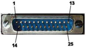
2. DB25:
DB25 adheres to the RS-232C interface standard. It has 25 pins as shown in the figure. The connector is "D" shaped, and easy to recognize. DB-25 is normally used in older computers, and not much used in modern day computers.
3. RJ-11:
RJ-11 is a 4-wire connector, commonly used with a modem. It should not be confused with bigger RJ-45 cable and connector. RJ-45 is commonly used for Ethernet network interface card (NIC).
Schematic of RJ-11 Connector
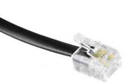
An RJ-11 Cable with Connector
| Pin # | Function |
| A1 | Ground |
| A2 | Rx (Data Input) |
| A3 | Tx (Data Output) |
| A4 | Vc (Power) |
4. RJ-45:
An RJ-45 connector has 4 pairs of wires as shown in the schematic diagram below. Note that an RJ-11 is a 4-wire connector, where as RJ-45 is an 8-wire connector.
RJ-45 connector schematic
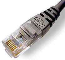
RJ-45 connector crimped to a cable.
RJ-45 connector is commonly used for Ethernet Networking ports. Devices that normally use RJ-45 ports include NICs, Hubs, Switches, and Routers.
There are basically two types of cables. One is Straight-through cable, and the other is Cross-over cable. Straight-through cables are used for connecting a network device to a work station. Cross-over cables are used for connecting a hub to a switch or a hub to another hub.
Parallel Ports:
1. DB-25
DB-25 connector is most commonly used in conjunction with a parallel printer. It has an 8 bit data bus as shown in the figure below.
| Pin # | Function |
| Pin 1 | Strobe |
| Pin 2 | Data Bit 0 |
| Pin 3 | Data Bit 1 |
| Pin 4 | Data Bit 2 |
| Pin 5 | Data Bit 3 |
| Pin 6 | Data Bit 4 |
| Pin 7 | Data Bit 5 |
| Pin 8 | Data Bit 6 |
| Pin 9 | Data Bit 7 |
| Pin 10 | Acknowledge |
| Pin 11 | Busy |
| Pin 12 | Paper End |
| Pin 13 | Select |
| Pin 14 | Auto Feed |
| Pin 15 | Error |
| Pin 16 | Initialize Printer |
| Pin 17 | Select Input |
| Pin 18 - Pin 25 | Ground (return for pins 0-7) |
The length of Parallel Printer cable usually limited to a maximum of 15 feet
Other Type of Parallel Ports:
Enhanced Parallel Port (EPP): The Enhanced Parallel Port (EPP) operates close to ISA bus speed and can achieve transfer rates up to 1 to 2MB/sec of data.
Enhanced Capabilities Port (ECP): The Enhanced Capabilities Port (ECP), is an additional enhanced Parallel port.
Download practice tests:
Download Sim-Ex™ Practice Exams for A+ Core 1
Download Sim-Ex™ Practice Exams for A+ Core 2
Related practice tests:
Sim-Ex™ Practice Exams for Network+
Sim-Ex™ Practice Exams for Server+
Sim-Ex™ Practice Exams for Security+
Disclaimer: Simulationexams.com is not affiliated with any certification vendor, and Sim-Ex™ Practice Exams are written independently by SimulationExams.com and not affiliated or authorized by respective certification providers. Sim-Ex™ is a trade mark of SimulationExams.com or entity representing Simulationexams.com.A+™,Network+™,Security+™,Server+™ are trademark of CompTIA® organization.