Before going ahead with Frame Relay protocol, and its operation, we discuss virtual circuits. Remember that a circuit provides connection between end nodes by means of an electrical connection. In data circuits, the term virtual circuit is also used in similar sense. A virtual circuit provides a logical connection between end nodes for the flow of information. There are two types of virtual circuits:
Permanent Virtual Circuit (PVC): PVC is a permanent connection between the end nodes (DTEs) within a Frame Relay network. The virtual circuit is always available irrespective of whether any data is being transmitted or not. This type of connection (PVC) is used when it is required to consistently transfer data between the end nodes. A PVC can have two operational states as given below:
Switched Virtual Circuit(SVC): A switched virtual circuits (SVC) provide temporary connection between end nodes (DTEs) across a Frame Relay network. An SVC communication session has four states:
If there is some more data to be transmitted at a later time, an SVC is negotiated again. SVCs are advantageous when you have burst traffic, and you don't want to block the network bandwidth for a given virtual circuit 24hours a day.
Unlike SVC, there is no call setup, and call termination procedures in PVC. This results in simple link management procedures, and more efficient data transfers.
Frame Relay Protocol: FR is an HDLC protocol based network. We have discussed HDLC in earlier sections, and the HDLC frame is given below. Other protocols that use HDLC frames include SDLC, Frame Relay, and X.25. They primarily differ in how the address and control bits in HDLC frame are used.
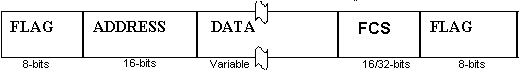
The different fields are explained below with respect to Frame Relay:
Flag (both opening and closing flags): 8 bits (01111110 or 7E hex)
Address (Also known as Frame Relay Header): It is a 16-bit field as given below.
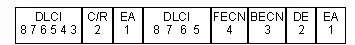
Data Link Connection Identifier (DLCI): The DLCI is 10-bit wide. DLCI identifies the virtual connection between the end node (a DTE device) and the switch (a DCE device).
C/R: The C/R bit says whether the frame is a command or response.
Forward Explicit Congestion Notification (FECN): This is a single-bit field that can be set to either 0 or 1 by a switch. Normally, FECN is zero. A value of 1 indicates network congestion in the direction of source to destination, known as Forward Explicit Congestion Notification.
Backward Explicit Congestion Notification (BECN): This is a single-bit field that can be set to either 0 or 1 by a switch in the FR network. Normally, BECN is zero. A value of 1 indicates that the FR network has experienced congestion in the direction of destination to source.
By using FECN and BECN, upper layer protocols can control the communication for efficient utilization of FR network.
Discard Eligibility (DE): This is set by the DTE device to indicate that the marked frame may be discarded in the event of network congestion. Discard Eligible frames are discarded first before removing frames that do not have DE bit set, in the event of network congestion.
Note that all FECN, BECN, and DE enable FR network congestion control by regulating the communication, and prioritizing traffic.
Extended Address (EA): The eighth bit of each byte of the Address field (header) is used to indicate the EA. If the EA value is 1, then the current byte is determined to be the last octet of the DLCI.
Data: This field contains encapsulated upper-layer protocol data. It has variable length up to 16,000 octets.
FCS (Frame Check Sequence) or CRC (Cyclic Redundancy Code): It is either 16 bits, or 32 bits wide. Frame Check Sequence is used to verify the data integrity. If the FCS fails, the frame is discarded.
Disclaimer: Simulationexams.com is not affiliated with any certification vendor, and Sim-Ex™ Practice Exams are written independently by SimulationExams.com and not affiliated or authorized by respective certification providers. Sim-Ex™ is a trade mark of SimulationExams.com or entity representing Simulationexams.com.CCNA™ is a trademark of Cisco® systems