1.0 Personal Computer Components
Serial Ports:
The serial port is an Asynchronous port which transmits data one bit of data at a time. Serial port hardware usually consists of a UART (Universal Asynchronous Receiver/Transmitter).
Most commonly used serial ports are given below:
1. DB9:
DB9 adheres to the RS-232c interface standard. It has 9 pins as shown in the figure. The connector is "D" shaped, and easy to recognize. The function of each pin is described below.
Outline Diagram of DB-9
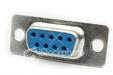
DB-9 Female Connector
Pin Description:
| Pin # | Pin Description |
| Pin 1 | Data Carrier Detect DCD |
| Pin 2 | Received Data RxData |
| Pin 3 | Transmitted Data TxData |
| Pin 4 | Data Terminal Ready DTR |
| Pin 5 | Signal Ground Gnd |
| Pin 6 | Data Set Ready DSR |
| Pin 7 | Request To Send RTS |
| Pin 8 | Clear To Send CTS |
| Pin 9 | Ring Indicator RI |
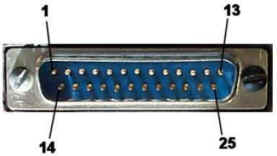
2. DB25:
DB25 adheres to the RS-232C interface standard. It has 25 pins as shown in the figure. The connector is "D" shaped, and easy to recognize. DB-25 is normally used in older computers, and not much used in modern day computers.
3. RJ-11:
RJ-11 is a 4-wire connector, commonly used with a modem. It should not be confused with bigger RJ-45 cable and connector. RJ-45 is commonly used for Ethernet network interface card (NIC).
Schematic of RJ-11 Connector
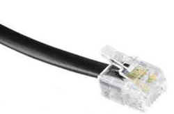
An RJ-11 Cable with Connector
| Pin # | Function |
| A1 | Ground |
| A2 | Rx (Data Input) |
| A3 | Tx (Data Output) |
| A4 | Vc (Power) |
4. RJ-45:
An RJ-45 connector has 4 pairs of wires as shown in the schematic diagram below. Note that an RJ-11 is a 4-wire connector, where as RJ-45 is an 8-wire connector.
RJ-45 connector schematic
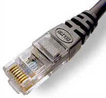
RJ-45 connector crimped to a cable.
RJ-45 connector is commonly used for Ethernet Networking ports. Devices that normally use RJ-45 ports include NICs, Hubs, Switches, and Routers.
There are basically two types of cables. One is Straight-through cable, and the other is Cross-over cable. Straight-through cables are used for connecting a network device to a work station. Cross-over cables are used for connecting a hub to a switch or a hub to another hub.
1. USB
USB stands for Universal Serial Bus. The most important features of USB bus include the following:
USB connectros can be broadly divided into USB A, and USB B. The difference between the two is in the physical layout of pins in the connector. Both are shown in the figure below.
| Pin # | Function |
| Pin 1 | +5V DC |
| Pin 2 | Data- |
| Pin 3 | Data+ |
| Pin 4 | Ground |
USB"A" plugs are used towards the host system and USB "B" plugs are used towards the USB device.
2. FireWire/IEEE1394
FireWire/IEEE1394 port provides data rates up to 400 Mb/sec. The standard is most suitable for transferring high volumes of information including video, and voice data.
Given below are some of the important features of IEEE 1394 standard:
4 PIN IEEE1394 (without Power)

A IEEE 1394 Connector schematic
| Pin | Function |
| Pin #1 | Twisted-pair B, differential signals, TPB- |
| Pin #2 | Twisted-pair B, differential signals, TPB+ |
| Pin #3 | Twisted-pair A, differential signals, TPA- |
| Pin #4 | Twisted-pair A, differential signals, TPA+ |
6 PIN IEEE1394 (with Power):
IEEE1394 6-pin connector schematic.
| Pin # | Function |
| 1 | Power, 18-28v no load. |
| 2 | Ground |
| 3 | Twisted-pair B, differential signals, TPB- |
| 4 | Twisted-pair B, differential signals, TPB+ |
| 5 | Twisted-pair A, differential signals, TPA- |
| 6 | Twisted-pair A, differential signals, TPA+ |
Parallel Ports:
1. DB-25
DB-25 connector is most commonly used in conjunction with a parallel printer. It has an 8 bit data bus as shown in the figure below.
| Pin # | Function |
| Pin 1 | Strobe |
| Pin 2 | Data Bit 0 |
| Pin 3 | Data Bit 1 |
| Pin 4 | Data Bit 2 |
| Pin 5 | Data Bit 3 |
| Pin 6 | Data Bit 4 |
| Pin 7 | Data Bit 5 |
| Pin 8 | Data Bit 6 |
| Pin 9 | Data Bit 7 |
| Pin 10 | Acknowledge |
| Pin 11 | Busy |
| Pin 12 | Paper End |
| Pin 13 | Select |
| Pin 14 | Auto Feed |
| Pin 15 | Error |
| Pin 16 | Initialize Printer |
| Pin 17 | Select Input |
| Pin 18 - Pin 25 | Ground (return for pins 0-7) |
The length of Parallel Printer cable usually limited to a maximum of 15 feet
Other Type of Parallel Ports:
Enhanced Parallel Port (EPP): The Enhanced Parallel Port (EPP) operates close to ISA bus speed and can achieve transfer rates up to 1 to 2MB/sec of data.
Enhanced Capabilities Port (ECP): The Enhanced Capabilities Port (ECP), is an additional enhanced Parallel port.
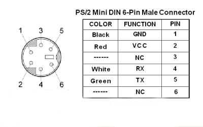
PS/2:
The PS/2 port is most frequently used for connecting a computer mouse or keyboard to a PC. The PS/2 port is a mini DIN plug and contains six pins. Below is a picture of an actual PS/2 plug and pin description:
MIDI:
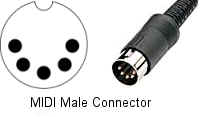
The MIDI protocol lets computers and electronic musical instruments (like digital keyboards and sequencers) share performance data with each other.
S/PDIF
Short for Sony/Philips Digital InterFace, is a serial interface for transferring digital audio from CD and DVD players to amplifiers and TVs. S/PDIF uses unbalanced 75 ohm coaxial cable up to 10 meters with RCA connectors or optical fiber terminated with a Toslink (Toshiba link) connector.
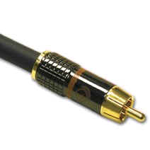
An S/PDIF connector cable.
Disclaimer: Simulationexams.com is not affiliated with any certification vendor, and Sim-Ex™ Practice Exams are written independently by SimulationExams.com and not affiliated or authorized by respective certification providers. Sim-Ex™ is a trade mark of SimulationExams.com or entity representing Simulationexams.com.A+™ is a trademark of CompTIA® organization.